


How to identify SMT component’s polarity
Special attention should be paid to the polarity components in the whole PCBA processing process, because the wrong orientation components will lead to batch accidents and the failure of the whole PCBA board. Therefore, it is very important that engineering or production personnel to understand SMT polarity components.
1. Definition of polarity
Polarity refers to that the positive and negative or the first pin of component, and the positive and negative or the first pin of PCB are in the same direction. If the direction of the component and the PCB board doesn’t match, it is called reverse bad.
2. Polarity identification method
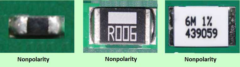
a. Chip resistor has nonpolarity
b. How to identify Capacitor polarity
- Nonpolarity of ceramic capacitor
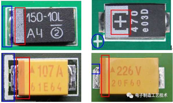
- Tantalum capacitors have polarity. Positive marking of PCB and components: 1) color band marking; 2) “+” marking; 3) diagonal marking
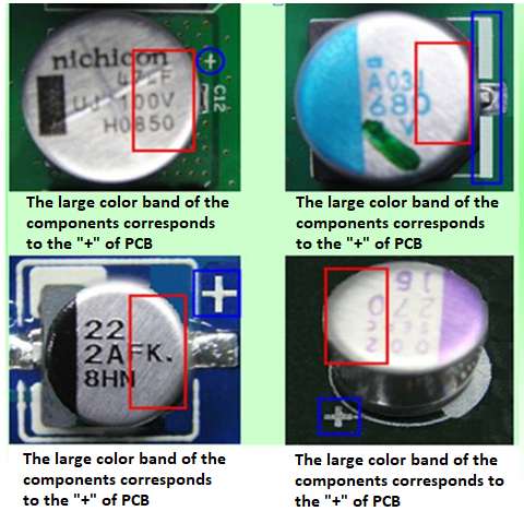
- The electrolysis and capacitance of aluminum have polarity. The component mark: color band represents negative; PCB mark: color band or “+” represents positive.
3. How to identify inductor polarity
There are no polarity requirement for package of chip coil and other two welding ends.
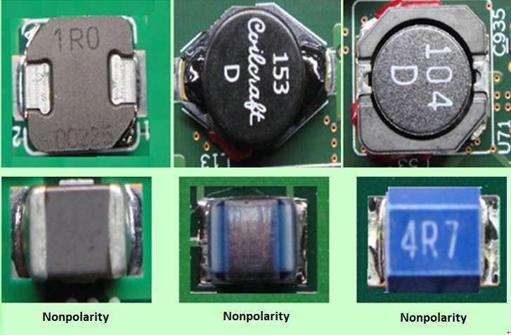
Multi pin inductors have polarity requirements. Component mark: dot / “1″ stands for polarity point; PCB mark: dot / circle / “*” stands for polarity point.
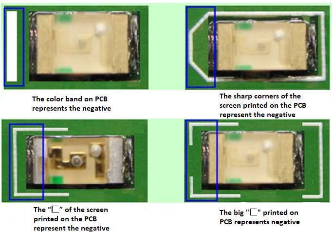
4. How to identify light emitting diode polarity
SMT surface mounted LED has polarity. Negative mark of component: green is negative; negative mark of PCB: 1) vertical bar, 2) color band, 3) sharp corner of silk screen, 4) “匚”of silk screen.
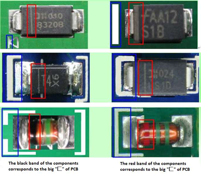
5. How to identify diode polarity
SMT surface mount diode has polarity. Negative label of component: 1) color band, 2) groove, 3) color to marking (glass); negative to marking of PCB: 1) vertical bar to marking, 2) color to marking, 3) silk screen sharp corner, 4) “匚” to marking
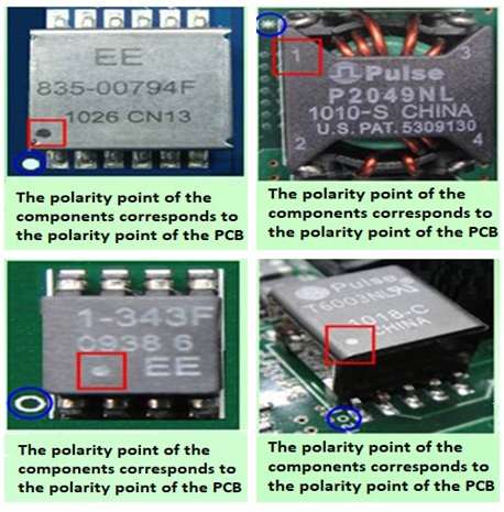
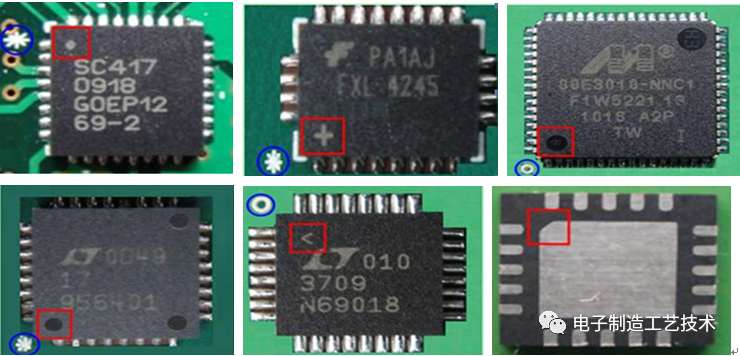
6. How to identify IC (Integrated Circuit) polarity
SOIC type packaging has polarity. Polarity indication: 1) color band, 2) symbol, 3) concave point, groove, 4) bevel.
SOP or QFP type packaging has polarity. Polarity indication: 1) concave / groove to marking, 2) one of the points is different from the other two or three points (size / shape).
QFN type packaging have polarity. Polarity to marking: 1) one point is different from the other two points (size / shape), 2) beveled edge to marking, 3) symbol to marking (horizontal bar, “+” , dot)
7. How to identify (BGA)Ball Grid Array polarity
component polarity: concave point / groove mark / Dot / circle to mark; PCB polarity: circle / Dot /1 or A / diagonal to mark. The polarity point of the component corresponds to the polarity point on the PCB.
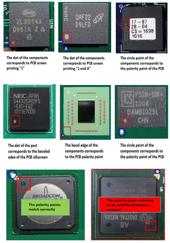
(The text of the picture is from left to right, and from top to bottom: the dot of the components corresponds to PCB screen printing “1″, the dot of the components corresponds to PCB screen printing “1 and A”, the circle point of the components corresponds to the polarity point of the PCB, the bevel edge of the components corresponds to the PCB polarity point, the circle point of the components corresponds to the polarity point of the PCB, the polarity points match correctly, polarity point matching error, and the direction is reversed )
PCBFuture can providing high quality bare printed circuit boards and printed circuit board assemblies at very lower cost, outstanding service and timely delivery. A team with more than 2 decade of experience have developed a reputation for consistently delivering quality products and services on time. If you have any questions, please contact sales@pcbfuture.com freely.
Post time: May-22-2021